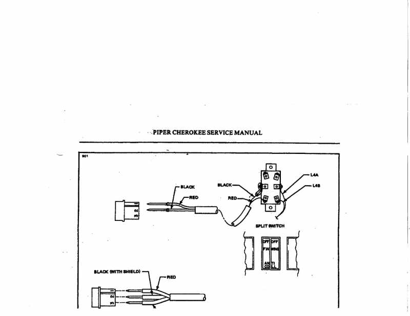
Hello Steve and thanks for your prompt reply. After I emailed you, I went out the maintenance hanger at the airport for some “hangar flying”. As luck would have it, there was a late model Archer in for maintenance. I poked my head under the panel, took some photos and low and behold, it also had the jumper between the center lugs. It was almost as mine was originally wired except for the lower lugs, I could see the labeling on the wire as L4A. They were crossed opposite of what mine was. I went back to my plane, made a new jumper, rewired as per your instructions. Everything now works as it should. You would think that Piper would have labeled the diagrams as Whelen system with another diagram for XYZ brand of strobe system. Just wondering if there is somewhere I could have found that info. I am probably not the first person led on a wild goose chase searching for a correction. Thanks for all your help. Your instructions were “right on”! Thanks again!
STROBE LIGHT SPLIT SWITCH
-
Hi Jerry;
If you take a look at figure 4 F 14, you’ll see that wire L4A is power to the switch from the bus and L4B is power out of the switch to the Nav lights. The ground for each light is at the lights.
In order to power the other side of the switch (the strobe side) there has to be power to that side of the switch; so I suggest you re install the jumper from the center lug on the right (viewed in the drawing) to the center lug on the left.
The power to the strobes will be off the lower lug on the left side of the switch.
The ground for the strobes will be at the flashers.I think what’s confusing is the illustration. It’s not for the Whelen strobes. Forget the black wire at the left side center connector. That center connector is where the power comes to the switch from the jumper from the center connector on the right side.
Just connect the power wire to the Whelen strobes to the bottom lug on the left side.Let me know if this suggestion works.
Steve
I own a 73 PA-28 140 (28-7325031) that had a panel upgrade about a year ago. At that time I had the radio shop install a split 2 position rocker switch with a single lead. I am now upgrading my interior so I felt this would be an opportune time to complete the strobe system. I installed a 2 light Whelan PS and I’m keeping the original rotating beacon. I attached the 1 furnished lead that was installed previously to to the PS, turned on the master and the strobes and beacon were operating. Unfortunately, the strobes all came on when I turned on the master. Illustration 4E9 in the piper service manual clearly shows how this should be wired. When I poked my head under the panel I saw a jumper lead between the L4A lug of the switch and the center lug on the left side of the switch (illustration attached). L4A is the feed wire from the buss. The previous installed wire was also attached to the center lug on the left side the switch. I removed the jumper moved the connections around as per the drawing. I grounded the left side center lug to the airframe. The #2 wire(black) in the Molex connector shows this grounded. I moved the red wire to the bottom left lug of the switch. I really expected this all to work, but alas, it didn’t. We tested the switch and determined that the strobe side of the switch was not getting any power from the beacon side of the switch. We both agreed that the split switch was at fault and I purchased a new switch. We installed the new switch, wired as per the diagram……..Nothing but beacon only. We must be missing something with this. The diagram is so simple but something isn’t right. I do not want to install a single on/off switch for both strobes and beacon as I’ve heard others do. I would like to have them work independently as Piper had designed.Any suggestions to correcting this would greatly be appreciated. Thanks in advance for your suggestions.
Attachments:
- You must be logged in to reply to this topic.


