
A look inside your aircraft’s vacuum system.

When the earliest airplane gyroscopic instruments were introduced, the only available source for air pressure to spin them was an outside-mounted air venturi. The venturi accelerated the ram air pressure produced by forward flight through a narrowed opening. The instrument hoses were connected to the venturi at the point of lowest pressure, creating a vacuum that pulled a steady stream of air through the instruments.
Although some VFR-only planes still use this arrangement, the trouble with this setup is that the amount of vacuum is low until certain airspeeds are reached, and the venturi can become ineffective due to ice buildup during inflight icing conditions.
In the late 1930s, air pumps were developed that were engine-driven, creating air suction (or pressure) as soon as the engine was started. These early air pumps were lubricated with engine oil and would later be called “wet style” pumps.
In the 1960s wet pumps were largely replaced with the “dry” pumps. Dry vacuum pumps are self-lubricating and have an oil-free exhaust flow that reduces belly deposits and provides a much cleaner source of air pressure on aircraft models that use the vacuum pump exhaust for inflating de-ice boots. The dry air pumps are also a little less expensive and weigh about half as much as the older wet style pumps.
How the pump works
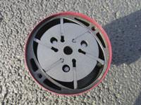
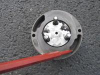
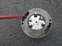
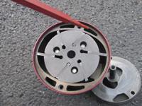
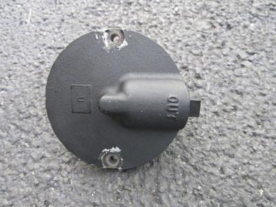
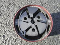
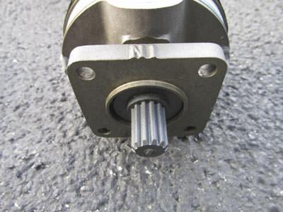
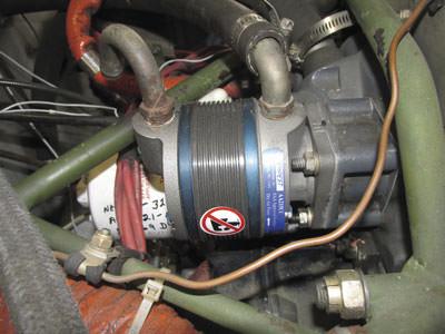
The standard dry air vacuum pump consists of a rotating carbon vane assembly housed in an elliptically-shaped aluminum housing. The carbon vane assembly is powered by the engine accessory drive. The outer pump housing has an air inlet port on the front of the pump and an exhaust port on the rear.
The rotor portion of the carbon vane assembly has slots that house the carbon vanes themselves. The vanes are free to slide inward and outward as the rotor spins. Centrifugal force keeps the vanes in contact with the inner wall of the pump housing.
As the rotor spins, the vanes in the rotor slide in at the narrow section of the housing and slide outward to their maximum extension at the widest points of the elliptical housing they travel in.
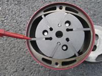
The intake air from the instrument system is routed through the pump fitting to ports in the forward section of the pump housing. The ports are open at the bottom and sides of the pump housing to allow air to flow in as the carbon vanes are beginning to move outward in the rotor slots.
The air is then compressed as its compartment is compacted while the vanes rotate toward the narrow part of the housing. It is then accelerated out of exhaust ports located in the narrowest part of the ellipse. This all occurs through the first 180 degrees of rotation.
As soon as the vanes move past the exhaust openings, they scoop in intake air from a second set of intake air openings—and the entire process is completed again in the second 180 degrees of rotation.

How the vacuum system works
The airflow through a common single-engine aircraft vacuum system begins under the instrument panel. Air enters the system through a central pleated paper filter. The filter is located under the instrument panel. Ambient air is drawn into and through it solely due to the suction of the attached hoses going to the vacuum pump. It then flows through the attitude and heading indicators before reaching the system regulator.
The system regulator combines additional air as needed to the intake of the pump so that the system suction stays within the parameters the regulator is adjusted to maintain. (The regulator has a slipover “sock” style filter to protect the pump from any particles that might be drawn in with the ambient air.) Airflow continues through the pump and then is exhausted into the engine compartment on most models. Aircraft with de-ice boots utilize the pump’s exhaust air to inflate the boots.
The artificial horizon and directional gyro flight instruments are usually connected to the vacuum system in parallel with each having its own connections to the intake and vacuum air so that even if one instrument were to fail or become clogged, the other one still functions because it has its own connection to the air source.
A suction gauge is connected in the system so that it measures the air pressure difference between the supply line from the central paper intake filter and the outlet of one of the instruments prior to reaching the system regulator. The pressure drop from the intake air (which is close to atmospheric pressure on nonpressurized planes) and the air being drawn into the regulator is measured in inches of suction.
Most vacuum systems are designed to operate with around five inches of suction with the engine rpm at or near a cruise setting. If the system suction is too high, it can cause excessive wear in the gyros and the vacuum pump. If the vacuum system suction is too low, the instruments will not give reliable indications.
Twin-engine aircraft with two vacuum pumps also utilize various check valves so that a failure of either pump doesn’t cause the system to lose vacuum.

Vacuum pump failure
Vacuum pumps are built to run for several hundred hours—but one of the biggest downfalls of dry air vacuum pumps is that when they do fail, it is usually suddenly and without warning.
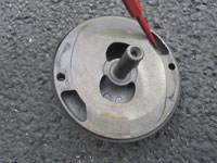
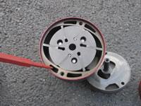
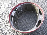
The carbon vanes, by design, will wear down over time as the pump operates. Eventually, the vanes can become so short that they will either hang up, or come completely out of their slots as they rotate through the wide part of the ellipse and cause the sudden stoppage of the rotor assembly in the pump.
Also, the inner wall of the aluminum housing is prone to developing indentions and slight deformities as the vanes slide in and out against it. These indentions can cause one or more of the vanes to hang up and break apart.
Some vacuum pump manufacturers have incorporated a wear indicator port on the side (or on some models, the rear) of the pump. The ports allow access to check the length of the vanes, which can help catch an impending failure. (The pumps are designed with a nylon drive coupling that shears in two if the pump does lock up, so that the gears in the engine accessory case are not damaged when a pump fails.)
Contamination within the vacuum pump can also cause a sudden failure. The hoses used in the vacuum system can become dried and brittle over time. If internal pieces of hose begin to flake off, or if any contaminants get into the vacuum system downstream of the central paper filter, they go straight through the pump. The small sock filter on the regulator only filters the ambient air that is added to the flow as the pressure is regulated—not the already-filtered air from the instruments.
Some mechanics use Teflon tape or some type of sealing compound on the pipe-threaded instrument and pump fittings in the vacuum system. Teflon tape and other sealants are not recommended for use at all in the instrument system, because pieces of the tape or sealant can make their way into the system as the fittings are threaded into place and these may eventually get sucked into the pump.
The filters themselves can become sources of contamination over time if they aren’t regularly replaced. The sock filter in particular can become so dried-out and brittle that pieces of it may be ingested into the airflow. Most vacuum pump manufacturers require replacement of all filters at the time of installation in order for the pump warranty to be valid.
Solvents used to wash down the engine during maintenance are very damaging to vacuum pumps. If any of the solvent material gets into the pump, it causes the graphite powder—which is always present from normal wear—to turn into a paste that gums up the inside of the pump. Pump manufacturers recommend completely covering the pump with a resealable plastic bag and tie wraps before washing down the engine.
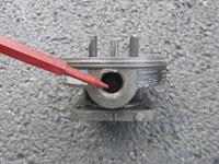
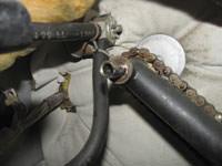
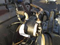
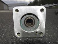
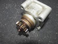
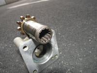
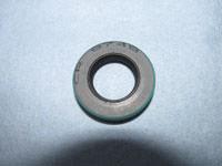
Oil contamination is also a big culprit in premature vacuum pump failures. One of the biggest sources of oil contamination typically comes from a leaking oil seal on the engine accessory case adapter drive. The adapter drive gear in the accessory case is made with a splined hollow shaft that spins the vacuum pump drive coupling.
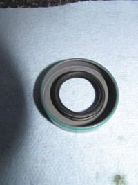
There is an oil seal that the vacuum pump drive gear is inserted through. It naturally wears out over time because the shaft is spinning inside of it. Once the oil seal begins to degrade, it allows oil—under pressure—to head straight for the pump drive coupling and into the pump itself. This excess oil causes a gummy paste to form that eventually binds the pump.
Kinked fittings or hoses can cause excess wear on a pump by forcing it to work harder than it should to maintain vacuum suction. (If suction levels begin to degrade, lots of mechanics simply increase the suction by adjusting the regulator—instead of determining the exact cause of the suction loss. If a system starts to become sluggish, the root cause should be determined before simply cranking up the regulator.)

Vacuum pump replacement
Vacuum pumps are typically straightforward to replace.
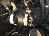
The hoses and fittings on the old pump should be removed before the mounting nuts are removed, so the pump is held tightly in place as the hoses are pulled off the fittings.
Most vacuum pumps are mounted on four studs and secured with plain nuts and lock washers. Typically one or more of the nuts are difficult to access with a normal type of wrench, and vacuum pump manufacturers make a specially-curved wrench that helps gain a little access.
The old mechanic’s trick for breaking loose the nuts that are in a tight place involves using a long flat blade screwdriver placed on the loosening side of the nut. The screwdriver is then gently tapped with a small hammer to break the nut loose.
A new oil seal should be installed anytime a new vacuum pump is installed—whether the old oil seal is leaking or not. The seals wear out over time and require periodic replacement. They are also reasonably priced (around three dollars each), so cost is not a consideration.
If an owner is having a shop replace the pump, it is best to specifically request that the oil seal be replaced in addition to the pump, because some mechanics don’t replace them unless they are leaking.
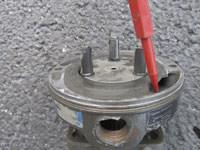
There are two gaskets that require replacement: the one between the vacuum pump and its drive housing, and the one between the drive housing and the engine accessory case.
Be sure to check the aircraft maintenance manual to be sure the new vacuum pump being installed is the correct model number. Pumps rotate either counter-clockwise or clockwise as viewed from the rear of the pump and case. (The rotation is specified as “CC” or “CW” in the part number.) Putting the wrong pump on will cause it to spin opposite the direction the rotor slots and vanes are designed for, and the pump will fail in short order—if not immediately.
The vacuum system hoses and system regulator that are just upstream from the vacuum pump must be checked for contamination whenever a failed pump is being replaced. Pieces of the old pump vanes often get sucked backward into the suction hose—against the normal direction of airflow—as the pump fails because the system still retains a lower pressure for a few seconds even though the pump has stopped.
If the hose isn’t cleaned or replaced after a sudden pump failure, carbon and vane parts will be sucked into the new pump upon startup.
If compressed air is used to blow out the lines, be sure all the instruments are disconnected so they don’t get blasted with excessive pressure or contaminated by unfiltered particles. Also, as the manufacturers specify, all of the vacuum system filters should be replaced at each pump replacement.
Owners that fly a lot of hard IFR might consider periodically replacing a vacuum pump based on time in use alone, even if that pump is operating properly.
Many new aircraft are shifting toward a glass panel configuration, but the benefit of the vacuum pump system is that it will still power the pneumatic instruments even in the event of a total electrical failure. A little preventive maintenance and upkeep on the vacuum system can help owners be assured that the indications on the gauges can be trusted in the clouds.
Know your FAR/AIM and check with your mechanic before starting any work. Always get instruction from an A&P prior to attempting preventive maintenance tasks.
Jacqueline Shipe grew up in an aviation home; her dad was a flight instructor. She soloed at age 16 and went on to get her CFII and ATP certificate. Shipe also attended Kentucky Tech and obtained an airframe and powerplant license. She has worked as a mechanic for the airlines and on a variety of General Aviation planes. She’s also logged over 5,000 hours of flight instruction time. Send question or
comments to editor@www.piperflyer.com.
