
Engine oil provides lubrication and cooling for an aircraft’s engine. Ensuring your oil pressure remains “in the green” is one of the most important things you can do for your engine’s health and longevity. Oil pressure in an engine is like blood pressure in a human. Both are important indicators of internal health, and both should be kept within proper parameters to ensure longevity.
Operating pressure
The normal oil pressure range for most Lycoming engines is between 60 to 90 pounds per square inch (psi). This range is indicated by the green arc on the oil pressure gauge. The maximum oil pressure allowed for short durations is 115 psi on most models. The maximum allowable pressure has increased over the years from 100 to 115 psi. The top red line on most oil pressure gauges is 100 psi. The lowest allowable limit for oil pressure with the engine operating at idle with hot oil is 25 psi, which is indicated by the lower red line on most oil pressure gauges.
Lycoming generally sets the operating pressures for cruise rpm on their factory-rebuilt engines to between 75 to 85 psi. Most new, rebuilt or overhauled engines require a slight adjustment of the oil pressure to finalize the setting once the engine break-in process is complete.
Oil flow through a typical Lycoming engine
Lycoming engines use a “wet sump” oil system. This simply means that the oil sump is mounted under the engine and oil flows by means of gravity back to the sump after it has been pumped through the engine. The sump is completely open on the top so that all areas of the engine can drain back into it, and it functions like a large drain pan. “Dry sump” systems have a separate dedicated oil tank. Oil is routed to the tank once it has completed its course through the engine.
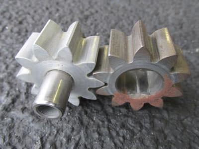
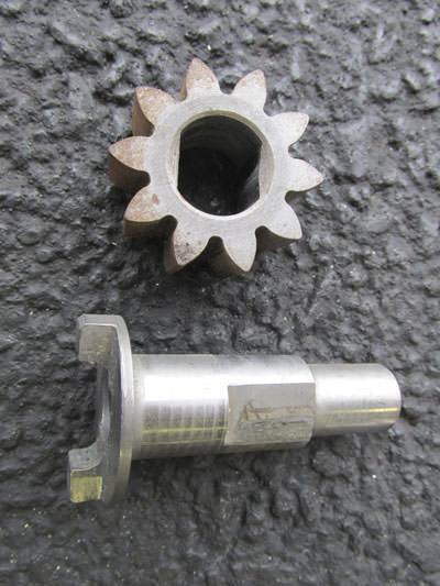
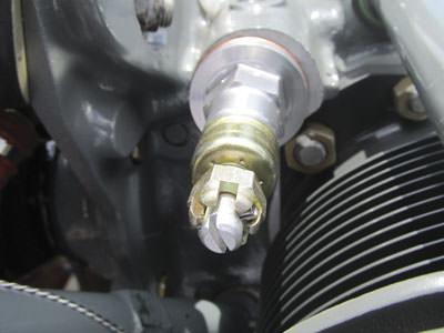
The Lycoming oil pump is located in the accessory housing. It consists of an aluminum outer body and two steel impellers, one of which is gear-driven off the crankshaft. (See photos 01, 02 and 03 on this page.) It produces oil pressure in direct proportion to how fast the gears spin. At higher engine rpm, the pump produces more oil pressure than at low engine rpm.
Oil is drawn up through the suction screen in the sump and through the oil pump impellers. The oil is then routed to the thermostatic bypass valve (also called a vernatherm valve).
Oil continues to flow to the oil filter adapter on the accessory case and through the oil filter (or screen if the engine is not equipped with an oil filter). From the filter, oil is routed to the oil pressure relief valve. The oil pressure relief valve is located on the top right side of the crankcase. It relieves excessive oil pressure by opening a drain port to the sump to bypass some of the oil flow if oil pressure gets too high.
Oil then travels to the crankshaft bearings and through predrilled passageways in the case to lubricate the internal engine parts through either pressure or splash lubrication. After completing its course, the oil drains back to the sump.
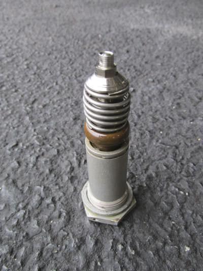
Thermostatic bypass valve
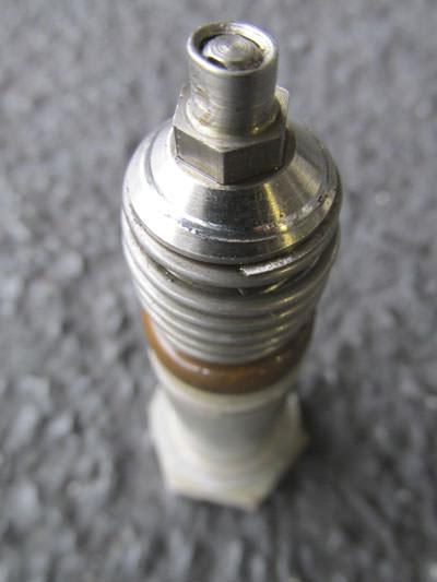
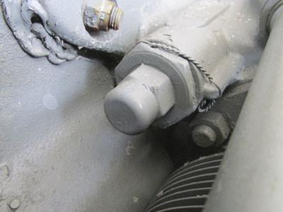
The thermostatic bypass valve is similar to a thermostat in an automotive engine cooling system. (See photo 04, far left.) The valve remains open when the oil is below 180 F, allowing the oil to bypass the passage to the oil cooler. As the oil heats up past 180 F, the vernatherm expands and eventually contacts its seat, forcing oil to pass through the oil cooler.
An engine that has abnormally high oil temperature may have a thermostatic bypass valve that is not expanding as it should with increased temperature, or that is not seating properly due to a worn seat. The valve seat wears over time and typically gets a worn groove that gets slightly worse every time it closes. If the valve gets excessively worn it allows some oil to bypass the oil cooler even when the oil is hot. (See photo 05, left.)
Some of the older bypass valves had retaining nuts that were improperly crimped during manufacture. Lycoming issued Mandatory Service Bulletin 518C that contained instructions for performing a heat treatment using a special Loctite to permanently secure the nuts in place. Valves that have had the Loctite treatment are typically inscribed with an “L” near the part number to indicate they have been repaired.
As of August 2016, Lycoming no longer recommends this repair. Mandatory Service Bulletin 518D supersedes 518C and states that valve repair/rework is no longer allowed. Older-style valves with loose crimp nuts should be replaced.
Engines that suddenly develop an oil temperature problem may have one of the older-style valves with an improperly crimped nut that has come completely loose. Lycoming Service Instruction 1565 provides the procedure for replacement.
Oil pressure relief valve
The oil pump is a direct drive pump. This means that the pump impellers spin in direct relation to engine speed and produce oil pressure that also varies directly with engine speed. At high engine rpm, the pump produces far more pressure than the engine is designed to handle. Therefore, a pressure regulator must be incorporated into the system to keep pressures high enough at low engine speeds to protect the bearings and low enough at high engine speeds to prevent rupturing or damaging any of the engine components.
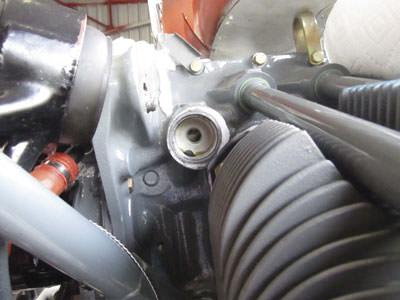
The oil pressure relief valve (or oil pressure regulator) is located on the top right side of the crankcase; behind the number three or the number five cylinder, depending on whether it’s a four- or six-cylinder engine. (See photo 06, page 34.)
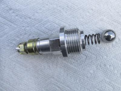
The oil pressure relief valve is very basic in its method of relieving excessive oil pressure. It consists of an aluminum housing with a strong spring, which presses against a steel ball. The spring keeps the ball seated. As oil pressure builds beyond the amount the spring is adjusted to maintain, the ball is forced off its seat by the excessive pressure. This exposes a passageway (bypass) that directs excess oil back to the sump, relieving some of the oil pressure.
There are three types of housings. The latest style has an adjustable spring seat that can be cranked in or out as needed by means of an attached castellated nut on the end of the shaft. The older styles were adjusted by removing the housing and spring and adding or subtracting washers behind the spring to increase or decrease pressure. (See photos 07, 08 and 09 on page 34.)
The oldest style housing was short and had an adjustment of zero to three washers maximum. (See photo 10, page 36.) The longer housing allowed up to nine washers maximum to increase spring tension. (See photo 11, page 36.) Each added washer increases oil pressure approximately 5 psi. On the externally adjustable models, one turn in (clockwise) increases oil pressure approximately 5 psi.
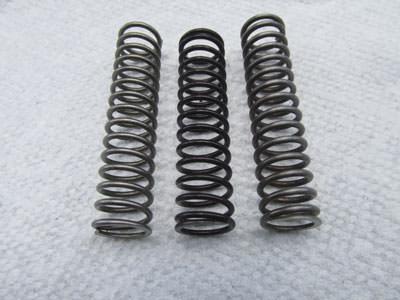
There are also springs of varying tensions and lengths which can be interchanged if the above adjustments do not yield the desired results. Some of the springs are color-coded to help differentiate them from one another. The most commonly used ones are the white LW-11713 springs (thick, heavy springs that are used to increase oil pressure at all settings), the 68668 (purple springs that are short and have much less tension than the others), and the 61084 non-color-coded spring that is standard equipment on most regulators. (See photo 12, page 36.)
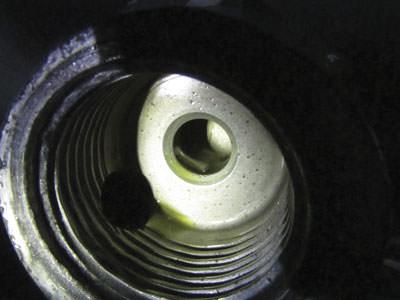
One of the more common problems with the oil pressure regulators is with the seat that the steel ball contacts every time it closes. The seat is simply a machined aluminum section of the crankcase itself on most engine models, and over time it can become worn, especially if the ball is not contacting the seat dead in the center. If oil pressure varies excessively with engine rpm, especially at lower engine speeds, the regulator ball and seat may not be closing properly. Poor contact allows some of the oil to bypass back to the sump when it shouldn’t. (See photos 13, 14 and 15 on pages 36 and 38.)
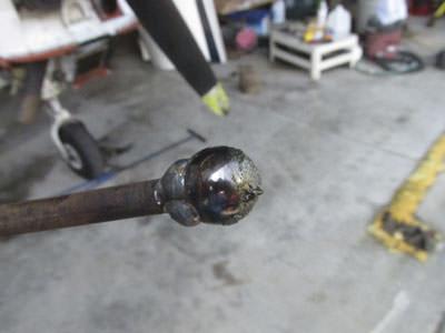
If the cast aluminum seat has an irregular wear pattern in it, Lycoming recommends rigging up a makeshift tool out of an old ball welded to a steel rod that is thick enough to be struck with a hammer, then inserting the newly made tool squarely against the seat and giving it a couple of sharp hammer strikes to reform the seat, allowing a tighter fit between a new ball and the seat.
The field method of repairing a worn or non-concentric seat that most mechanics employ is to use the same tool mentioned above, but instead of striking it with a hammer, they use a tiny bit of valve grinding compound on the ball to re-lap the seat. Care must be taken to prevent the compound from getting into any of the oil passageways during the process, but overall this method tends to work well to reform the seat and regain a good seal between the ball and seat. (See photo 16, page 38.)
Some of the earlier engines did have a replaceable seat insert that could be changed out and replaced if it was worn, but the most common seat is the cast aluminum type mentioned above.

Oil pressure gauge
The oil pressure gauge on many airplane models consists of a mechanically-actuated “Bourdon tube.” The Bourdon tube is a somewhat rigid, coiled, hollow tube. The tube is connected to a small oil pressure line and as oil pressure increases, the tube is stretched to a straighter, uncoiled position. The amount that it stretches varies directly with the pressure. An attached needle and gear mechanism allows the varying pressure to be read on the oil pressure gauge. These mechanisms can get dirty and stick, or the gearing mechanism can get worn and not indicate correctly. A shaky needle is often caused by a worn gear mechanism in the gauge.
Some aircraft use an oil pressure transducer or sending unit that looks similar to the oil pressure switch used for Hobbs meter installations. It is a unit that has an oil pressure line piped into one side, and electrical wires connected to the other side. Pressure is converted to an electrical signal and wires are run to a gauge that displays the oil pressure reading.
The oil pressure in most Lycoming engines is taken off the top rear accessory case. The oil pressure fitting has a reduced orifice in the outlet to the gauge. This helps prevent catastrophic oil loss if the oil pressure line or gauge begins to leak. Carbon or dirt can sometimes clog the orifice and cause an abnormally low oil pressure reading.

Troubleshooting oil pressure problems
Most oil pressure problems can be adjusted back to normal with the regulator or traced to a malfunctioning regulator or gauge. Sometimes, the trouble is a little more difficult to repair.
The first step in correcting abnormally high or low oil pressure should be to double-check the pressure reading with a separate pressure gauge to confirm that the oil pressure really is too high or low. Check the oil temperature, too. Low oil pressures will produce increased oil temperatures, and vice versa; overly high temperatures thin the oil and can cause a lower-than-normal oil pressure reading.
Excessive internal engine clearances due to excessive wear or a bearing failure can become so great that the output of the pump is insufficient to fully pressurize the oil system. This is typically a worst-case scenario and lower oil pressure readings occur gradually over time.
Excessive oil pump clearance between the impellers and the housing can also cause degraded oil pressure output.
Oil viscosity plays a role in oil pressure as well. A slightly lower than normal oil pressure may be caused by using too thin an oil depending on where the plane is operated.
A clogged suction screen or partially blocked passage between the screen and pump can also cause low oil pressure.
A higher-than-normal oil pressure reading, especially one that occurs suddenly, can be indicative of a blockage somewhere in the system, usually downstream of the pump.

Conclusion
Oil pressure readings should be consistently monitored so that any deviation from normal operation can be detected and remedied quickly. Consistent, normal oil pressure from startup to shutdown helps assure that an engine will run reliably for a long time.
Know your FAR/AIM and check with your mechanic before starting any work.
Jacqueline Shipe grew up in an aviation home; her dad was a flight instructor. She soloed at age 16 and went on to get her CFII and ATP certificate. Shipe also attended Kentucky Tech and obtained an airframe and powerplant license. She has worked as a mechanic for the airlines and on a variety of General Aviation planes. She’s also logged over 5,000 hours of flight instruction time. Send question or comments to editor@www.piperflyer.com.
RESOURCES >>>>>
Lycoming Mandatory Service Bulletin 518D
https://www.lycoming.com/node/15796
Lycoming Service Instruction No. 1565A
https://www.lycoming.com/content/service-instruction-no-1565-a
