
Finding and repairing a broken circuit is the subject of this fourth installment of A&P Jacqueline Shipe’s DIY series.
Among the many preventive maintenance items listed in FAR 43 Appendix A that a pilot may legally perform on his or her plane is “troubleshooting and repairing a broken landing light circuit.” This specific entry is the only reference to electrical circuit troubleshooting on the list.
Most electrical circuits for lights or pitot heat, etc. are fairly straightforward, while a wiring harness for a unit like a panel-mounted GPS can be very complex. This article will focus on the tools and expertise required to successfully troubleshoot a landing light.
Study the diagram
On any electrical circuit, the best troubleshooting tool is always the current wiring diagram pertinent to the model and serial number of the airplane. Learning how to read a wiring or system schematic can help a pilot not only in performing repairs, but also in understanding how a unit or system actually works.
Everything electrical has to have a power source and a ground to operate. Some circuits contain numerous switches and circuitry that work in conjunction with each other to provide the needed power or ground.
When a fault occurs, knowing how to dissect that circuit into sections—and understanding when and where voltage or a ground is supposed to be present—is essential. The wiring diagram provides all the needed information.
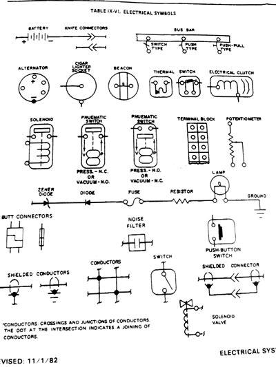
There are standard symbols used on these diagrams to indicate different components in a circuit. There is always a symbology chart somewhere in the maintenance manual wiring section that lists the symbols and the components they represent.
Some of these symbols are drawn to look somewhat like the component they represent, such as a circuit breaker. Switches, contactors and relays are generally shown on diagrams in the open (or “relaxed”) condition unless otherwise noted.
To get familiar with a specific circuit, follow the flow of a circuit on a diagram and consult the chart when you see an unknown symbol. It doesn’t take long before the symbols all become familiar.
The parts of a circuit
Exterior light circuits are some of the most straightforward circuits on any plane, and the diagrams provide good practice for folks first learning to read a wiring schematic. Generally, it is best to start at the power source in the diagram and read down from there.
In figure 9-35 on page 24, the Piper Comanche landing light circuit, power comes from the bus bar to a 20-amp circuit breaker, which is a shared breaker for two separate landing light circuits. The number 14 indicates that the wire size for that section is 14 gauge.
L1A and L2A indicate the wire numbers; “L” representing a lighting circuit. (Each original wire on a plane is stamped multiple times along its entire length with the appropriate wire number, which helps tremendously.)
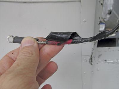
Both switches are shown in the open or “off” position. Coming out of each switch is the “B” section of each wire, still 14 gauge, up to a knife connector. Past the knife connector is the “C” section of each wire up to the terminal on the bulb itself.
The “D” section starts at the opposite terminal on the bulb and goes to ground. This section of wire is a little heavier duty as indicated by the fact that it is 12-gauge wire.
The wire gauge refers to how big its cross-section is; the smaller the number, the fatter and heavier duty the wire is. Starter and battery wires, for example, are large and heavy duty, generally six gauge or lower. Larger diameter wires can carry much more current than smaller diameter wires.
The airframe itself is generally used to provide a ground on most planes. The exact point where a wire for a circuit is connected to the airframe for a ground is usually not too far from the electrical component itself.
The airframe should be clean, and the wire terminal should be free of corrosion to ensure there is a resistance-free path for an electrical flow to ground.
Check the bulb first
First, be sure that any wires being checked are not touching any other wires or the airframe. Don’t allow any metal tools to touch both a live wire and the airframe at the same time.
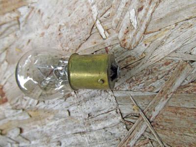
In the landing light circuit, the quickest and easiest place to go to troubleshoot an inoperative bulb is to check the bulb itself.
After removing individual bulbs from the plane, measure the resistance across the terminals with a multimeter set to ohms. This is a very simple task for landing or taxi light bulbs.
Navigation lights and several of the interior light bulbs utilize a base that inserts into a socket. The small raised area at the bottom of the base is the positive contact point, and the base of the bulb is the ground contact point on these bulbs. A good bulb will show continuity; the resistance varies a little depending on the type of filament it has.
Strobe bulbs are different; they can only be tested by an operational check. To check a strobe bulb, put the suspect bulb in a known good circuit, turn it on and see if the bulb works. If one wing strobe bulb works but the other doesn’t, switch the bulbs and you’ll immediately know if it’s the bulb or something else in the circuit that’s causing the trouble.
Check these things next
The two main checks that are required when troubleshooting a circuit are for voltage and a ground. Voltage is a measurement of the potential amount of electric power coming in to a certain point. It is not an indication of how much power is actually flowing.
Amperage measurements give an indication of the actual amount of power (current) that is flowing. Most meters only measure voltage, but some do have amperage settings.
Voltage is easier to measure because it can be checked anywhere in the circuit by placing the meter in parallel with the circuit. Amperage is harder to read because the meter has to be placed in series within the circuit, and the circuit has to be complete so that current is actually flowing.
Voltage
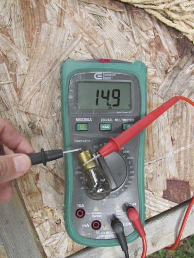
Voltage and resistance can be easily measured with an electrical multimeter. There are many different manufacturers of multimeters; even the most inexpensive ones are generally good enough to troubleshoot most electrical issues.
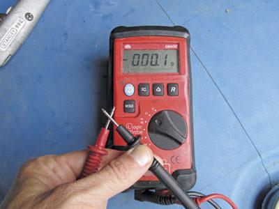
Before taking any measurements, it is a good idea to set the meter to the lowest ohms setting and touch the test leads together. This tests the connection of the leads to the meter and also the continuity of the test lead wires as well as the internal resistance of the meter. The reading should be zero ideally, but in any case it shouldn’t be much over one ohm.
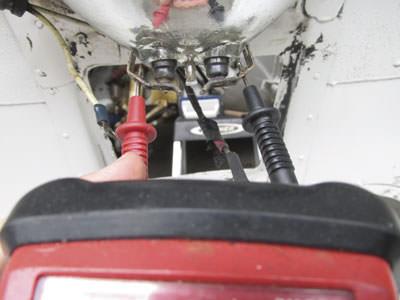
When the aircraft battery is on and the landing light switches are closed (i.e., turned on), there should be 12 volts at the terminal of the L1C and L2C wires. There should also be a very low resistance path to ground, which is measured on the L1D and L2D terminals.
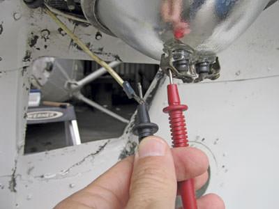
In the landing light circuit, voltage can easily be measured by placing the positive probe of the multimeter on the light terminal for the L1C or L2C wire (depending on which bulb is being checked) and the negative probe on a clean, bare metal area of the airframe for a ground. (Some owner-pilots use a small alligator clip to connect the black lead off the multimeter to a spot on the airframe. —Ed.)
With the appropriate switch flipped on, the voltage reading should be approximately the same as battery voltage if the circuit is working properly.
Amperage
Most of the time, a voltage measurement is all that is needed to be assured that power is being received, but it is good to know how to check amperage.
An electric motor that is operating a little slower than normal or is on the verge of shorting out typically begins to draw an excessive current load. A high amperage reading will also be present if there is too much resistance to motion in the mechanical apparatus the motor is trying to move.
Flaps that are binding, or a landing gear retraction or extension mechanism that is not properly adjusted will cause a motor to draw a high current load and get hot. Checking for a higher than normal amperage reading can allow you to detect a malfunction and fix it before it causes a total failure.
Amperage measurements are also useful to confirm that a component is receiving the full amount of electrical energy it needs to operate. Most of the time, voltage readings are sufficient for this, but there are some circumstances where a voltage indication can be misleading.
A wire that is barely connected or a switch that has badly burned contacts can still make enough of a connection to show full battery voltage at points in the circuit beyond, but will not be able to actually carry enough amperage to operate different components downstream. This can cause a lot of confusion, but is a fairly rare circumstance.
If all other checks pass with proper voltage and a good ground being indicated, and a known unit that is operable still won’t function, it would be prudent to see how much amperage the unit is getting; there could very well be a poor connection in the circuit somewhere upstream, even though the voltage readings are correct.
Ground connection
Ground connections are measured in ohms of resistance. Generally a reading of two ohms or less is indicative of a good connection to ground; readings that are five ohms or higher are cause for some concern.
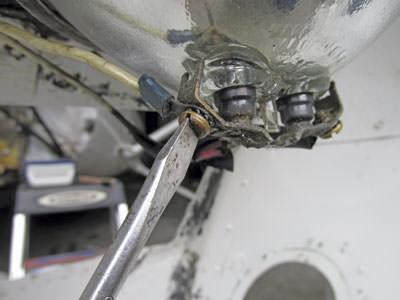
The airframe itself is used to ground most electrical circuits. The airframe often develops corrosion, which can cause excessive resistance in ground connections. Usually disconnecting a ground wire and cleaning the terminal and contacting airframe with 220 grit sandpaper or an abrasive pad (i.e., Scotch-Brite) clears it right up.
With a little practice and persistence, pilots will be able to interpret wiring diagrams, a multimeter will become easier to use, and electrical problems will seem less complex.
Most electrical issues can generally be traced to a problem that is fairly easy to fix. Knowing how to troubleshoot a circuit and read a schematic will save a pilot/owner both time and money in the long run.
Know your FAR/AIM and check with your mechanic before starting any work.
Jacqueline Shipe grew up in an aviation home; her dad was a flight instructor. She soloed at age 16 and went on to get her CFII and ATP certificate. Shipe also attended Kentucky Tech and obtained an airframe and powerplant license. She has worked as a mechanic for the airlines and on a variety of General Aviation planes. She’s also logged over 5,000 hours of flight instruction time. Send question or comments to editor@www.piperflyer.com.
RESOURCES >>>>>
Voltmeter and multimeter tools
– PFA supporters
